
|
Would a #5 rebar in the front cell of the Omni Block provide the same structural strength as using on #5 in the Insultech 5x5 core? Or would you have to run some engineering calculations to determine if this is the case? The Omni block shows placing 2 bars in the 2 ½” core holes front and back - - but the question is, can we eliminate the #5 bar in the rear core hole and still achieve the same structural strength as the Insultech block using one #5. The core hole being so much smaller with the grout, we were thinking that this probably would not provide the same strength? What are your thoughts as a structural engineer? No, The #5 does not provide as much strength because the distance between the center of the bar and the compression face of the masonry is not a far and the strength depends on that. However, the bending strength in the other direction is considerably more. Alternating the side that the steel is on could make a big difference in the overall bending strength when checked in both directions.
0 Comments
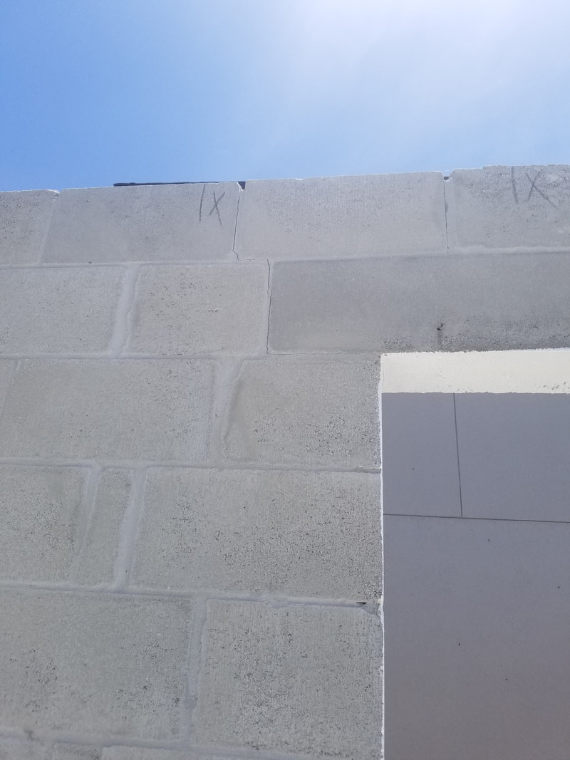
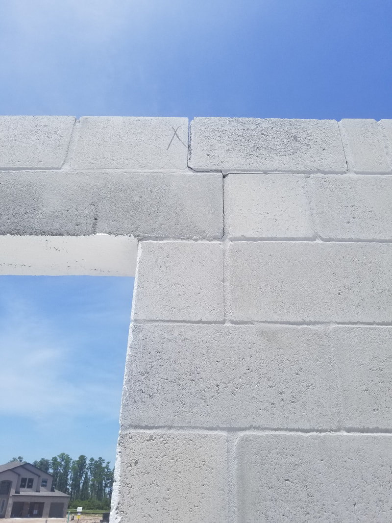
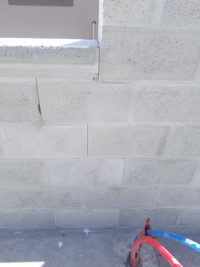
The attached photos show residential structures with cracking at the corners of significant openings (over 6 ft). First, is this cracking "normal" or is there a material defect? Secondly, is this a structural problem for the home? Third, what is the recommended repair? The pictures provided (see below) show cracks under the precast header bearing at what appears to be both ends of an opening. These cracks then turn and extend up to the top of the wall through the course above the precast in a stair step fashion. The third picture provided shows cracking under the end of a precast sill which then extends from the lower right hand corner of the opening down the wall in a stair step fashion. My response to this inquiry is based strictly on the three pictures provided. There may be other extenuating circumstances that I am not aware of. The pictures provided are so indicative of classic masonry shrinkage cracking that I intend to catalog and use them in future presentations to show where cracking usually shows up in structures where shrinkage of the masonry has not been addressed by either horizontal reinforcing or properly placed control joints. There are three important considerations to keep in mind when working with either concrete or concrete masonry - it's gray, it gets hard AND IT CRACKS. The cracking can be caused by movement (such as foundation failure), expansion and contraction due to temperature differential or drying shrinkage. Of these three, drying shrinkage is the by far and way the most common and MUST be addressed if random cracking is to be prevented. Concrete materials shrink when they loose moisture. Concrete poured under water does not shrink as long as it remains submerged. 50 years later if you pulled it out of the water and let it dry out it would shrink the normally expected amount. An exaggerated visual to keep in mind is that of a sponge drying in the sun. The normal masonry shrinkage expected from Florida aggregates is around .025% or around 0.3 inches in 100 feet. When the material is restrained from shrinking (such as when it is attached to a foundation) it is "stretched" by the normal shrinking process and this creates internal stress. If the concrete or masonry mortar shrinks before it has sufficient strength to resist these stress - cracking results. On of the most common locations for drying shrinkage cracking to occur is at the corners of openings. The reason is that mother nature views a section of the wall where a large part has been removed (you know - like an opening) as the perfect place to "joint" the wall. Recommended practices at openings thus calls for a control joint to be created adjacent to openings (almost exactly as mother nature has positioned these). As an alternative to control jointing at opening corners the steel over and under the opening can be extended into the adjacent wall sections, usually by around 24 inches. My take on the cracks shown in the pictures is that they are permanent control joints in the structure. As long as the horizontal and vertical steel required by the designer is in place I would expect them to cause no significant detrimental effect on the structural capacity of the wall. They are now your control joints, picked by mother nature herself, and repair would be to simply treat them as such. They should be routed out and stuffed with a backer rod then caulked with a one part polyurethane sealant and painted over (just the joint area - not the entire wall) with an elastomeric.
Links to additional Information:
NCMA Tek 10-02C1 - Control Joints for Concrete Masonry Walls - Empirical Method We have an odd size cell and wanted to know the max bar size we could use in that cell? The cell is 5" long and 2 1/2" wide. This is the info from the code on the size of reinforcing you can have in a cell (from current 2016 TMS 402). Looks like the max bar for Allowable Strength design for a 5" x 2 1/2" cell is a #7 and the Max bar for Strength Design is a #5. Allowable design is currently the predominate design procedure in Florida. A #7 bar is the largest bar that I personally recommend for 8” masonry.
For walls designed with Allowable Stress Design (denotes vertical steel)
For walls designed with Strength Design (does not denote vertical steel – thus would apply to vert or horz)
The architect is specifying the product DRY-BLOCK by gcp applied technologies as an integral waterproofing admix to be added to the block that are to be covered with a direct applied stucco. Is this what the industry would recommend? The masonry industry and the stucco manufactures in Florida clearly DO NOT recommend the use of an integral waterproofing agent in masonry to be covered with direct applied stucco. This is not specific to the DRY-BLOCK product but applies to ANY integral waterproofing agent added to the block during the manufacturing process.
The reason is simple - integral waterproofing agents negatively effect the bond between the block unit and the stucco coating. This bond is one of the most important aspects direct applied stucco coatings. The problem is that good stucco bond depends on absorption of cement and water, out of the stucco, into the pores of the block. The integral waterproofing agents are an excellent product for preventing exactly this type of water movement. Integral waterproofing in the masonry is highly recommended for single-wythe masonry walls which are not covered with direct applied stucco. They would also be appropriate for masonry covered with stucco attached to lath that is then mechanically attached to the block. In the case of direct applied stucco, the stucco itself is the primary waterproofing barrier protecting the wall. Stucco has proven itself an effective waterproofing barrier by both experience and testing. Can 6" masonry be used to satisfy the impact resistance criteria in Florida?The FBC, 6th edition, Building, Section 1626.4.1 allows for 8" hollow masonry to meet the impact criteria for the HVHZ (Dade and Broward). Although there is no mention of 6" masonry 1626.4.4 allows for 2" of reinforced concrete to meet the requirements also.
Common sense would grant that solid grouted 6" masonry is going to perform better than 2" of poured concrete but again it is not mentioned directly. That being said, FEMA P-320 Safe Room Const Plans specify 6" masonry with a #5 bar in a grouted cell at 16" o/c. The more stringent FEMA P-361, Safe Rooms for Tornadoes and Hurricanes, 3rd Ed, March 2015 allows solid grouted 6" masonry with a #4 bar at 32" o/c. As a side note, we plan to submit a code change to include solid grouted 6" masonry in the "deemed to comply" list under 1626.4 in the 7th Edition FBC. It is not currently listed simply because the issue of its use rarely comes up. In summary, I can see no good reason why a building official would reject solid grouted 6" masonry as specified in P-361 as being acceptable for missile impact requirements in the HVHZ. I have an 8' freestanding masonry screen wall adjacent to a building. Should the building be connected or not to the enclosure wall? In one location there is a doorway in the screen wall almost adjacent to the building with only an 8" piece of masonry between the building and the door opening. This 8" piece of masonry sits on the building foundation. Should this also be connected to the building or not?If the wall is supported by an independent foundation I would definitely recommend putting a full separation control joint between the wall and the building to account for differential settlement of the two foundations. The short section of wall sitting on the building foundation is trickier. Since it sits on the building foundation it is unlikely that there would be any vertical movement between the wall and the masonry door jam. In this case I would recommend solidly attaching the door jam to the building wall. This would also give the wall some additional out of plane strength to resist wind loads applied to it from the door. This will, unfortunately, create a stress build up at the underside of the lintel where it sits on this short section of wall. The stress is from the screen wall changing length from moisture loss or temperature change OR the foundation supporting the screen wall settling at a different rate than the building foundation. This control joint would be a standard joint at the corner of opening that runs under the lintel bearing horizontally for 8" then turns and runs up to the top of the wall or the underside of the bond beam, whichever works structurally. If there is a vertical bar adjacent to the opening it can pass through the horizontal plane of the control joint (slip joint) without completely negating the value of the joint. Links to additional information:
NCMA TEK 10-2C - http://ncma-br.org/pdfs/130/TEK%2010-02C1.pdf Why do we mortar the cross webs on either side of a poured cell? If the cross webs aren't mortared what can be done after the fact, that is, after the wall is laid up but prior to it being grouted? The short answer is the obvious answer - the cross webs are mortared to keep the grout from leaking out of the cell being filled. We don't want the grout leaking out for a number of reasons. The important structural reason is that the fluid paste surrounding the pea rock would leak out during the filling and vibrating of the cells leaving the pea rock behind with empty void spaces around the rock at each joint. These void spaces, where the paste is gone and only the rock is left, are commonly know as "honeycombs" in construction. Honeycomb severely weakens hardened grout or concrete where it occurs. This would only apply to course aggregate grout mixes that contain pea rock. High slump fine aggregate grout mix, that contains only sand and aggregate, is going to simply flow through the joints with little or no segregation between the cement and the sand. This uncontrolled leaking of fine aggregate grout does not present a structural problem as much as a construction problem. The fine aggregate grout will actually fill the adjacent cells, costing the contractor more money for grout. The contractor will surely be more reluctant to vibrate the grout after initial water loss as the level of fine aggregate grout would continue to drop as the grout leaks out. Unfortunately, this code required final vibration is essential to make sure that grout bridging in the cell has not formed a hollow areas under the bridged area (see below). 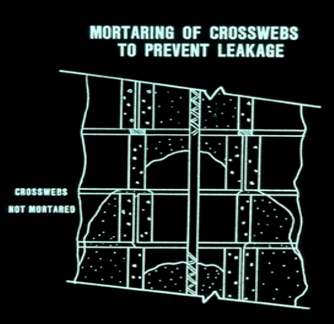 Also, the extra grout will increase the weight of the wall. Extra weight, other then in tall multi story buildings, is usually not a problem but should be verified with the designer. So, to answer the second part of the question directly, if the cross webs are not mortared the wall should be grouted with a fine aggregate grout with the proper slump (8" to 11"). It is essential that this fine aggregate grout be re-consolidated after the initial water loss to collapse any void areas. This will require additional topping off of the wall. Section 3.3 B. 4.b.2 of the TMS 602-16 code clearly calls out for the cross webs to be mortared. Fine aggregate grout should not and cannot become a substitute for proper construction. Links to additional documentation:
Grouting Concrete Masonry Walls http://ncma-br.org/pdfs/130/TEK%2003-02A.pdf What is the current code required geometry for a grade 60 #5 bar used in concrete masonry? Table 6.1.8 in the current TMS 402-16 (current referenced edition by the 6 Ed FBC) call for Grade 60 reinforcing for a #3 through a #8 bar to have an inside bend diameter of 6 db and an extension of 12 db. For a #5 bar the tip of the extension would then be 15 db or 9.37" from the face of the bar.
The project engineer has requested that ALL intersecting walls be laid up with 50% of the units overlapping at the corner. There are MANY intersecting walls and this prevents any wall from being run in an economical way as you have to continually stop and build your lead for the intersecting wall. What does the code require? An engineered masonry structure built in Dade or Broward is covered under the High Velocity Hurricane Zone section of the code, specifically section 2122. Section 2122.10 requires that "intersecting walls shall comply with TMS 402 section 5.1.1."
The referenced section gives three equivalent ways that intersections can be tied together. The first is that 50% of the units are overlapped at the corner. The second is that the wall shall be tied with a 28" long heavy steel "Z" anchor spaced at 48" vertically up the wall. The third method is to place a bond beam with .4 square inches of steel spaced at 48" vertically up the wall (you could use (2) #4 bars or (1) #6 bar). Since the plans and specs did not call out specifically for the 50% overlapping, any of the three methods would meet the requirements of the job and the code. How do Interpret Table 2 in TMS 602-16 in order to get the required net area compressive strength of an individual block for a specified f'm?I have included an article below explaining the increased block strength. It includes a copy of Table 2 so that you can reference it as you read this. The values of f'm are listed in the left most column and are labeled "Net area compressive strength of concrete masonry". Values are given in psi. The right hand two columns give the required Net area strength of the individual unit to achieve the given f'm. The far right column is to be used if Type "N" mortar is used to lay up the wall and the middle column is used if Type M or S mortar is used in the wall. Thus, an individual block with a net area strength of 2000 psi gives you an f'm = 2000 psi. An individual block with a net area strength of 3250 psi gives you an f'm = 2500 psi. And an individual block with a net area strength of 3900 psi gives you an f'm = 2750 psi. Links to additional information:
Update on Increased Design Strength of CMU 1-3-18 with Attachment 1.pdf |
Authors:

Categories
All
Archives
June 2022
|
 RSS Feed
Masonry Resources |
MAF Websites |

|
Masonry Association of Florida, Inc. |PO Box 24474 , Fort Lauderdale, FL 33307
Copyright © 2017. All Rights Reserved.
Sitemap
Sitemap