|
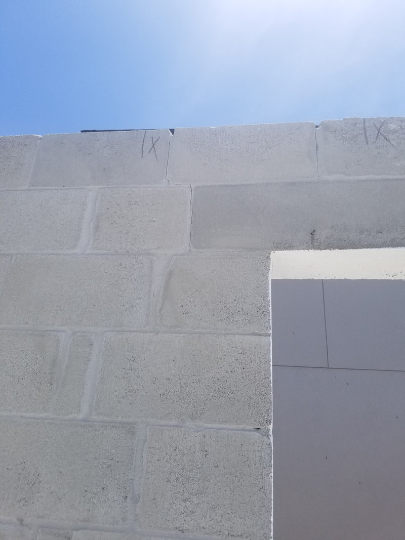
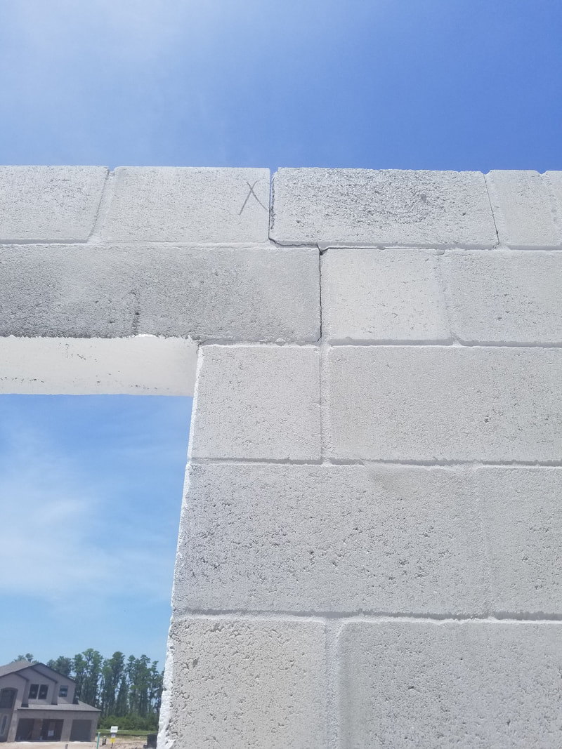
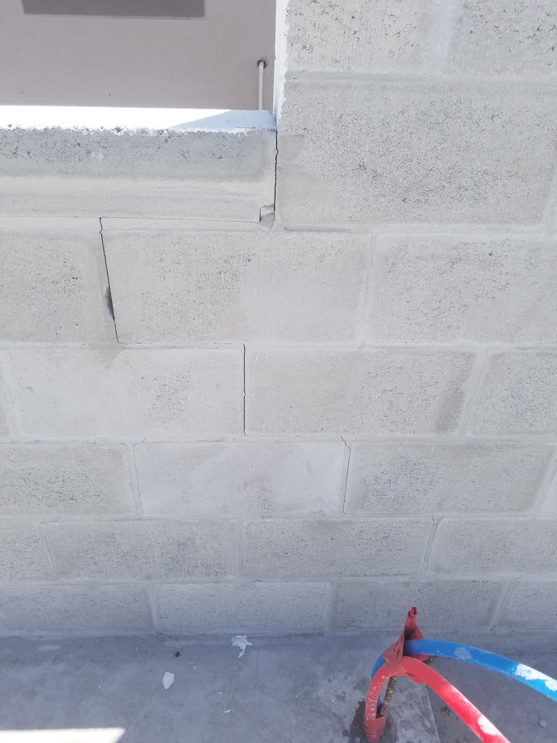
The attached photos show residential structures with cracking at the corners of significant openings (over 6 ft). First, is this cracking "normal" or is there a material defect? Secondly, is this a structural problem for the home? Third, what is the recommended repair? The pictures provided (see below) show cracks under the precast header bearing at what appears to be both ends of an opening. These cracks then turn and extend up to the top of the wall through the course above the precast in a stair step fashion. The third picture provided shows cracking under the end of a precast sill which then extends from the lower right hand corner of the opening down the wall in a stair step fashion. My response to this inquiry is based strictly on the three pictures provided. There may be other extenuating circumstances that I am not aware of. The pictures provided are so indicative of classic masonry shrinkage cracking that I intend to catalog and use them in future presentations to show where cracking usually shows up in structures where shrinkage of the masonry has not been addressed by either horizontal reinforcing or properly placed control joints. There are three important considerations to keep in mind when working with either concrete or concrete masonry - it's gray, it gets hard AND IT CRACKS. The cracking can be caused by movement (such as foundation failure), expansion and contraction due to temperature differential or drying shrinkage. Of these three, drying shrinkage is the by far and way the most common and MUST be addressed if random cracking is to be prevented. Concrete materials shrink when they loose moisture. Concrete poured under water does not shrink as long as it remains submerged. 50 years later if you pulled it out of the water and let it dry out it would shrink the normally expected amount. An exaggerated visual to keep in mind is that of a sponge drying in the sun. The normal masonry shrinkage expected from Florida aggregates is around .025% or around 0.3 inches in 100 feet. When the material is restrained from shrinking (such as when it is attached to a foundation) it is "stretched" by the normal shrinking process and this creates internal stress. If the concrete or masonry mortar shrinks before it has sufficient strength to resist these stress - cracking results. On of the most common locations for drying shrinkage cracking to occur is at the corners of openings. The reason is that mother nature views a section of the wall where a large part has been removed (you know - like an opening) as the perfect place to "joint" the wall. Recommended practices at openings thus calls for a control joint to be created adjacent to openings (almost exactly as mother nature has positioned these). As an alternative to control jointing at opening corners the steel over and under the opening can be extended into the adjacent wall sections, usually by around 24 inches. My take on the cracks shown in the pictures is that they are permanent control joints in the structure. As long as the horizontal and vertical steel required by the designer is in place I would expect them to cause no significant detrimental effect on the structural capacity of the wall. They are now your control joints, picked by mother nature herself, and repair would be to simply treat them as such. They should be routed out and stuffed with a backer rod then caulked with a one part polyurethane sealant and painted over (just the joint area - not the entire wall) with an elastomeric. Links to additional Information:
NCMA Tek 10-02C1 - Control Joints for Concrete Masonry Walls - Empirical Method
3 Comments
We have an odd size cell and wanted to know the max bar size we could use in that cell? The cell is 5" long and 2 1/2" wide. This is the info from the code on the size of reinforcing you can have in a cell (from current 2016 TMS 402). Looks like the max bar for Allowable Strength design for a 5" x 2 1/2" cell is a #7 and the Max bar for Strength Design is a #5. Allowable design is currently the predominate design procedure in Florida. A #7 bar is the largest bar that I personally recommend for 8” masonry.
For walls designed with Allowable Stress Design (denotes vertical steel)
For walls designed with Strength Design (does not denote vertical steel – thus would apply to vert or horz)
About eight months ago, you helped us getting some bond beam clarifications on a project we’re doing with PCL construction (see original email below). Recently we’ve encountered another bond beam issue on this project that we’re having a difficult time overcoming. The bond beam details show it located in the last course as seen it in typical applications (see attachment). Unfortunately, all of the overhead decks are installed and placed, making the installation of the bond beam on the top course very difficult to install and grout. We proposed to lower the bond beams by one course but we’re getting resistance from the engineer. PCL asked us to reach out to you in hopes that you could help shed some light into this and ease the engineers concerns that there are no structural concerns by doing this. Is this something you could take a look into and help us out with? The designer was hopefully thinking that the walls would be built first before creating this detail. As you are well aware the installation of the block is not the problem although a 3/4" space at the top would be more realistic and wouldn't effect the structural support of the wall by the very healthy 4x4x3/8 angles. If the engineer felt the need you could easily increase the number of anchors on each side from 2 to 3 to compensate for the additional moment from the wall. But that only addresses the installation of the masonry unit itself. The next problem is the installation of the grout which cannot be squirted into a 1/2" crack at the top of the wall. A common way to grout masonry walls under an existing slab is to core a 3" or 4" hole in the slab at 4' or so along the wall and grout the wall through those holes. It does sound like the engineer would like the top course grouted to increase the lateral load resistance. Failing being able to grout the top course through the cover slab you could engage some exotic method of porting and pumping a very fine grout mixture (it wouldn't meet C-476 but would work) into the wall at a lower level. The vertical steel is the easiest and you have probably done this many times. Just create a hand hold in the wall and slide a lapped bar up into the top course after it is laid in place. The horz steel as detailed is virtually impossible to install as you already know. This steel can only serve two purposes: 1) to span the 6' 8" laterally between the 4x4 side plants and 2) to provide horz reinforcement for crack control. The crack control reinforcement would actually perform better in the next course down ( or 3 or 4 courses down - makes no difference). Concern about the wall spanning laterally 6' 8" could be addressed by simply reducing the steel size to a #3 bar which could be slid into a hand hole in the top course. Another solution would be to distribute your latter supporting 4x4 angles down the length of the wall rather and a single 18" long piece at 8' o/c. Say... something like a 4x4x4" lg piece at 2' o/c. Your lateral bending between the supports then becomes insignificant and your (2) #5 bars in the second course down would take care of your crack control slightly more efficiently then if they were in the top course. Other than that you can form and pour the top course which still doesn't address how you get the concrete into it. I am honestly surprised that the engineer of record would not immediately recognize that he had created an extremely difficult (impossible) detail to construct and be helpful in rectifying the situation. If it has not already been done I would recommend providing him with the opportunity to come up with a reasonable engineering solution to the problem. Perhaps he has not been informed of the problem? What is the contractor's responsibility in specifying the strength of concrete? For example, would 2,500 PSI High Strength achieve the wind loads and 20ft wall heights? Or would 3,000 PSI CMU be needed for 20’ walls grouted 8” o.c.? That is why you hire a structural engineer! It depends... on the location, height of the wall section, vertical load, fixity of end conditions, openings, lateral support, etc. You're not designing the wall section, simply offering advice on the availability and cost of materials along with potential problems with the use of various materials. Without designing the wall section myself - which would include understanding the entire structure that the wall is a part of - it isn't possible to challenge or advise him on the design.
|
Authors:

Categories
All
Archives
June 2022
|
Masonry Resources |
MAF Websites |
Masonry Association of Florida, Inc. |PO Box 24474 , Fort Lauderdale, FL 33307
Copyright © 2017. All Rights Reserved.
Sitemap
Sitemap


 RSS Feed
