|
We have a project in WPB, the plans are calling out a Compressible Bond beaker at the control joints. We did not include this (Rubber, PVC CJ) in our contract, however, we did account for leaving the 3/8” of an inch as gap the control joint. Our walls are 8” CMU with a 2 hour fire rating. The EOR indicated that he wanted the joint to be 2 hr fire rated. My question is what determines the use of a rubber or PVC material verses the 3/8” gap for a control joint?? Are either of these fire rated? Please see the attached detail and EOR response. A "compressible bond breaker" in a control joint, as shown in his detail, would mean a backer rod. The backer rod or "compressible bond breaker" is pushed or "compressed" into the joint prior to caulking the 3/8" joint. It's purpose is to control the amount of caulking that goes into the joint, but more importantly, to "break" the 3 point "bonding" that occurs in the back of the joint and thus prevents the caulking from tearing open at this location.
The EOR is confused about the need for a COMPRESSIBLE material. He does want a fire rated system which is not what was called for either in the plans or in his response. His detail does not call out for a key way so that is clear. But it simply does not indicate what he is asking for. The language, as I have said, is simply another way of asking for a backer rod which he has already shown. He needs to go to https://submittalwizard.3m.com/# and pick a caulking that will give him the 2 hr rating he desires. A piece of "compressible rubber" does not carry a 2 hr fire rating. Whatever is in the control joint does NOT have to be compressible because the joint will never be compressed. Conc masonry walls shrink - always. He may be thinking about a clay brick product that would be EXPANDING and thus compressing the joint. You can fill masonry control joints with mortar if you want because they DON'T COMPRESS. Brick expansion joints have to be completely clean of mortar because the wall expands and the joint does get compressed. At this point he could solve the problem by simply changing to a fire rated caulking and eliminating the rubber filler. What he is asking for in his response carries no fire rating and is not what the words on the plans say. Another solution would be to provide a min of a 2" deep mortar joint on each side of the wall. After raking out the mortar for your backer rod and caulking you would have the usual 1 1/4" of mortar left in the joint - the same as every other head joint in the wall. This would meet the 2 hr rating by simply matching the amount of mortar as every other joint in a typical 2 hr masonry wall with face shell bedding. You would not have to go to the extra expense of using a fire rated caulking. I would be happy to discuss this with the EOR. Proper control joint construction is an area of common misunderstanding. It was nice to see that he had actually bothered to include control joints, an essential part of preventing random masonry cracking.
0 Comments
I am working with a major track builder who is having a problem a small vertical crack (approximately 1/64th inch) form from the top of the foundation to under the bond beam. The homes are 2-story. The 1st floor is masonry and the second floor is wood. The wall section is approx 40' long. What is the probable cause? The most likely cause is normal block shrinkage. Standard control joint spacing would call for a control joint about mid way in your 40' long wall. Sounds like mother nature has taken care of supplying that. You also might check for aggravating circumstances such as an interior partition at approximately that location with a vertical row of fasteners.
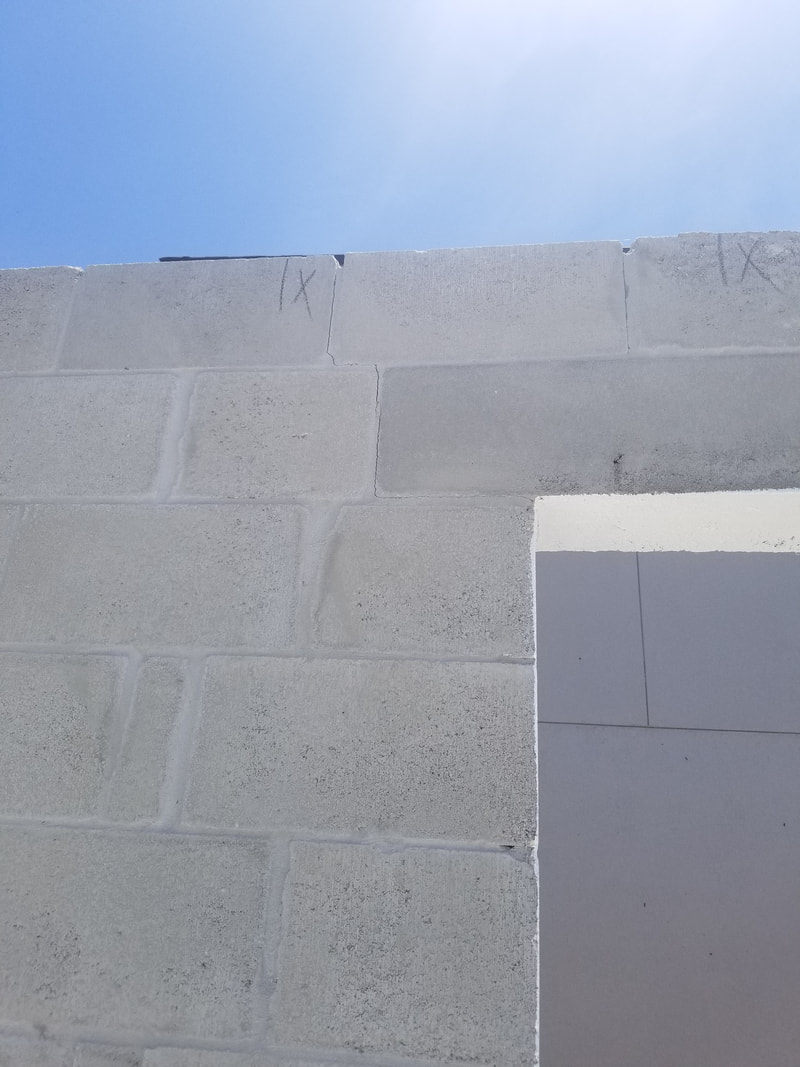
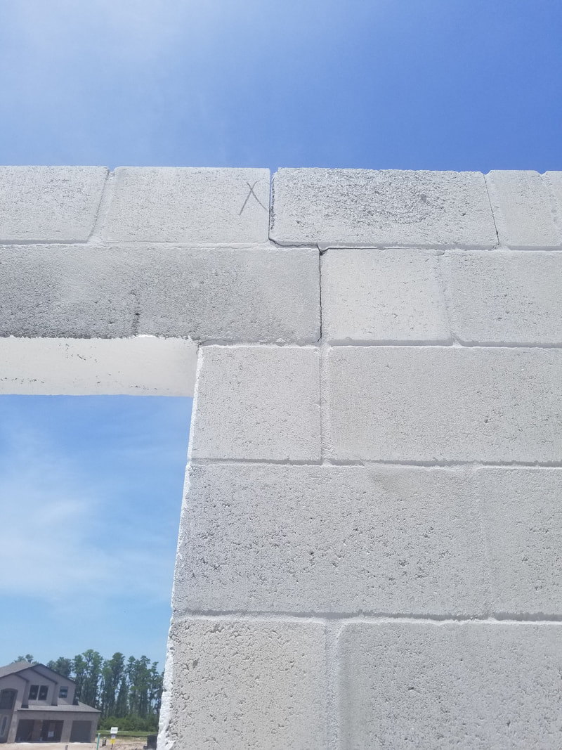
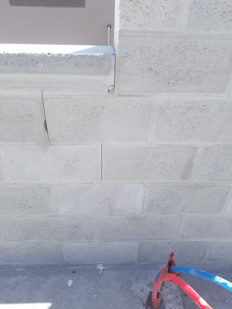
If the crack is the same width at the top as at the bottom my guess is that it is not caused by settlement. The attached photos show residential structures with cracking at the corners of significant openings (over 6 ft). First, is this cracking "normal" or is there a material defect? Secondly, is this a structural problem for the home? Third, what is the recommended repair? The pictures provided (see below) show cracks under the precast header bearing at what appears to be both ends of an opening. These cracks then turn and extend up to the top of the wall through the course above the precast in a stair step fashion. The third picture provided shows cracking under the end of a precast sill which then extends from the lower right hand corner of the opening down the wall in a stair step fashion. My response to this inquiry is based strictly on the three pictures provided. There may be other extenuating circumstances that I am not aware of. The pictures provided are so indicative of classic masonry shrinkage cracking that I intend to catalog and use them in future presentations to show where cracking usually shows up in structures where shrinkage of the masonry has not been addressed by either horizontal reinforcing or properly placed control joints. There are three important considerations to keep in mind when working with either concrete or concrete masonry - it's gray, it gets hard AND IT CRACKS. The cracking can be caused by movement (such as foundation failure), expansion and contraction due to temperature differential or drying shrinkage. Of these three, drying shrinkage is the by far and way the most common and MUST be addressed if random cracking is to be prevented. Concrete materials shrink when they loose moisture. Concrete poured under water does not shrink as long as it remains submerged. 50 years later if you pulled it out of the water and let it dry out it would shrink the normally expected amount. An exaggerated visual to keep in mind is that of a sponge drying in the sun. The normal masonry shrinkage expected from Florida aggregates is around .025% or around 0.3 inches in 100 feet. When the material is restrained from shrinking (such as when it is attached to a foundation) it is "stretched" by the normal shrinking process and this creates internal stress. If the concrete or masonry mortar shrinks before it has sufficient strength to resist these stress - cracking results. On of the most common locations for drying shrinkage cracking to occur is at the corners of openings. The reason is that mother nature views a section of the wall where a large part has been removed (you know - like an opening) as the perfect place to "joint" the wall. Recommended practices at openings thus calls for a control joint to be created adjacent to openings (almost exactly as mother nature has positioned these). As an alternative to control jointing at opening corners the steel over and under the opening can be extended into the adjacent wall sections, usually by around 24 inches. My take on the cracks shown in the pictures is that they are permanent control joints in the structure. As long as the horizontal and vertical steel required by the designer is in place I would expect them to cause no significant detrimental effect on the structural capacity of the wall. They are now your control joints, picked by mother nature herself, and repair would be to simply treat them as such. They should be routed out and stuffed with a backer rod then caulked with a one part polyurethane sealant and painted over (just the joint area - not the entire wall) with an elastomeric. Links to additional Information:
NCMA Tek 10-02C1 - Control Joints for Concrete Masonry Walls - Empirical Method I have an 8' freestanding masonry screen wall adjacent to a building. Should the building be connected or not to the enclosure wall? In one location there is a doorway in the screen wall almost adjacent to the building with only an 8" piece of masonry between the building and the door opening. This 8" piece of masonry sits on the building foundation. Should this also be connected to the building or not?If the wall is supported by an independent foundation I would definitely recommend putting a full separation control joint between the wall and the building to account for differential settlement of the two foundations. The short section of wall sitting on the building foundation is trickier. Since it sits on the building foundation it is unlikely that there would be any vertical movement between the wall and the masonry door jam. In this case I would recommend solidly attaching the door jam to the building wall. This would also give the wall some additional out of plane strength to resist wind loads applied to it from the door. This will, unfortunately, create a stress build up at the underside of the lintel where it sits on this short section of wall. The stress is from the screen wall changing length from moisture loss or temperature change OR the foundation supporting the screen wall settling at a different rate than the building foundation. This control joint would be a standard joint at the corner of opening that runs under the lintel bearing horizontally for 8" then turns and runs up to the top of the wall or the underside of the bond beam, whichever works structurally. If there is a vertical bar adjacent to the opening it can pass through the horizontal plane of the control joint (slip joint) without completely negating the value of the joint. Links to additional information:
NCMA TEK 10-2C - http://ncma-br.org/pdfs/130/TEK%2010-02C1.pdf Does the backer rod have to be larger or smaller than the joint that is being created? Backer rods are important to prevent 3-point bonding at the crack in the back of a joint. Also, they control the amount of caulking that a joint requires.
For expansion joints the backer rod should be just large enough to fit snugly into the control joint (which should be 3/8" for CMU walls). There should be about 1/2" of depth from the backer rod to the surface of the masonry wall. The backer rod should be snug enough to stay in place during caulking of the joint. |
Authors:

Categories
All
Archives
May 2024
|
Masonry Resources |
MAF Websites |
Masonry Association of Florida, Inc. |PO Box 24474 , Fort Lauderdale, FL 33307
Copyright © 2017. All Rights Reserved.
Sitemap
Sitemap


 RSS Feed
